Why the Krengo shell is shaped like this
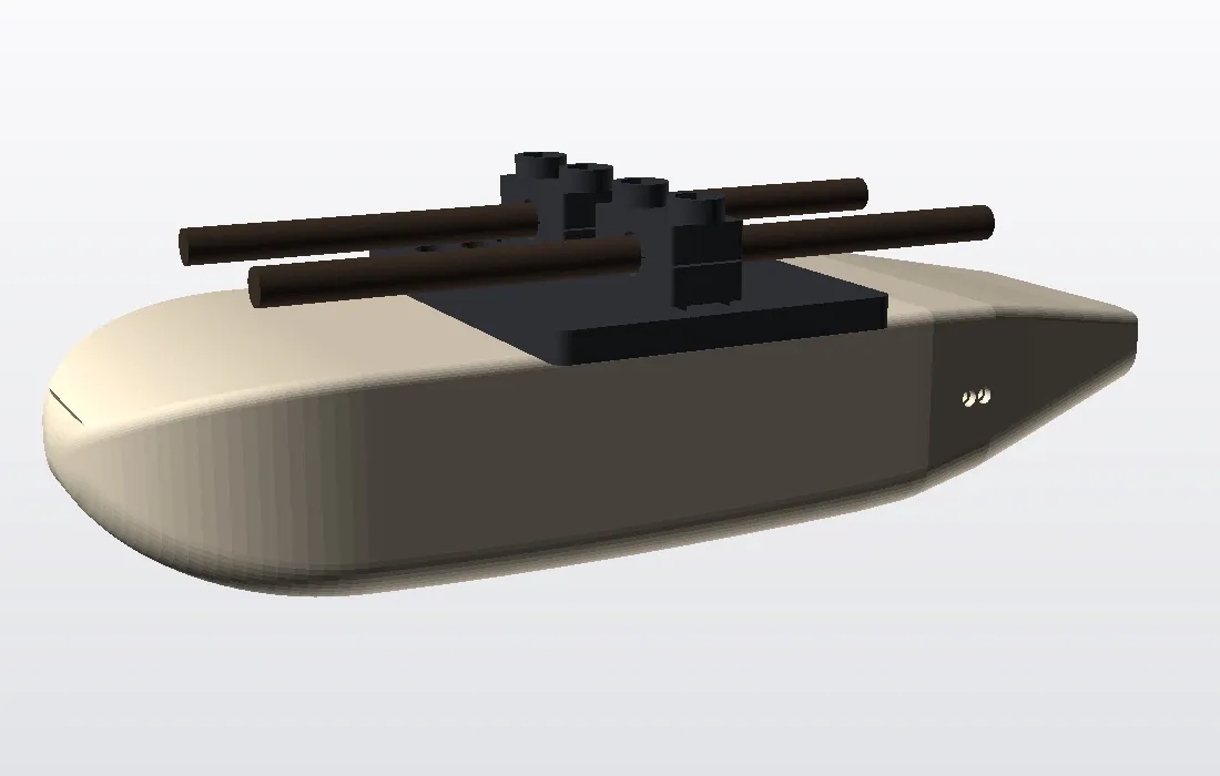
The Krengo logger lives under the saddle, behind the rider’s thighs. The shell around it is shaped from a handful of old aerodynamic rules: a round nose, a slow taper, a clean cut at the back. This page says which rules, where they come from, and what we have not measured.
What the shell has to do
The logger is a small box: 102 × 62 × 32 mm, with an ESP32, a motion sensor, a microSD card and a USB-C port. It clamps to the saddle rails. A bare box with sharp corners under the saddle is not a pleasing thing to ride with, and it is not the most honest shape for a bike that is supposed to be fast.
The goal is modest on purpose. The rider is by far the largest source of air resistance, and a 100 mm box cannot change that. The goal is to not make the air behind the rider worse. At about 35 km/h and 0.1 m, the Reynolds number is roughly 60,000 to 70,000. At that scale the flow separates easily, so a round nose and a gentle tail matter more than fine polish.
Six principles, and what we did with each
| Principle | Source | What the shell does |
|---|---|---|
| Sit in the wake | K3, K4 | The box stays under the saddle, behind the thighs, in the separated low-speed air. We did not move it lower, because wind-tunnel testing suggests low mounts on the seatpost are worse. |
| Do not add frontal area | K3 | The inner box is fixed by the electronics, so the outer shape follows it. The shell breaks this principle: frontal area grows from about 2,250 mm² to about 3,370 mm², roughly 50 % more. See the limits below. |
| Round front, no sharp edge into the flow | K1, K5 | The nose is a super-ellipse, 46 mm long, with its tip at half height. Floor and lid edges are rounded. |
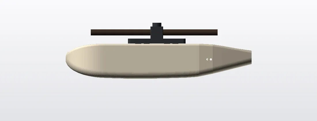
| Slenderness near 3:1 | K5 | Length to width is 220 / 83 = 2.65, and length to equivalent diameter is about 3.4. The width is locked by the 50 mm board and the antenna zone, so a true teardrop is not possible. |
| Tail no steeper than about 15° | K1, K2, K5, K6 | The tail tapers at 13° in plan, 11° at the floor and 10° at the roof, all under the 15° where flow starts to separate. |
| Cut the tail instead of running it to a point | K1, K2 | The tail ends in a flat wall at the service cover, a Kamm cut. The cut section is about 27 % of the maximum cross-section, a longer tail than Kamm’s classic 50 % because we kept the angle limit. |
Where it sits: in the rider’s wake
The shell sits under the saddle, where the rider’s legs and body already leave a large, turbulent, low-pressure wake. Wind-tunnel reports on bottles and bags suggest that things placed high, close to the rider’s back or seat, sit in that wake and cause less abrupt separation than things placed low on the seatpost. That is the reason the shell hangs where the clamp already puts it, and why it follows the rails rather than reaching for a more exposed spot.
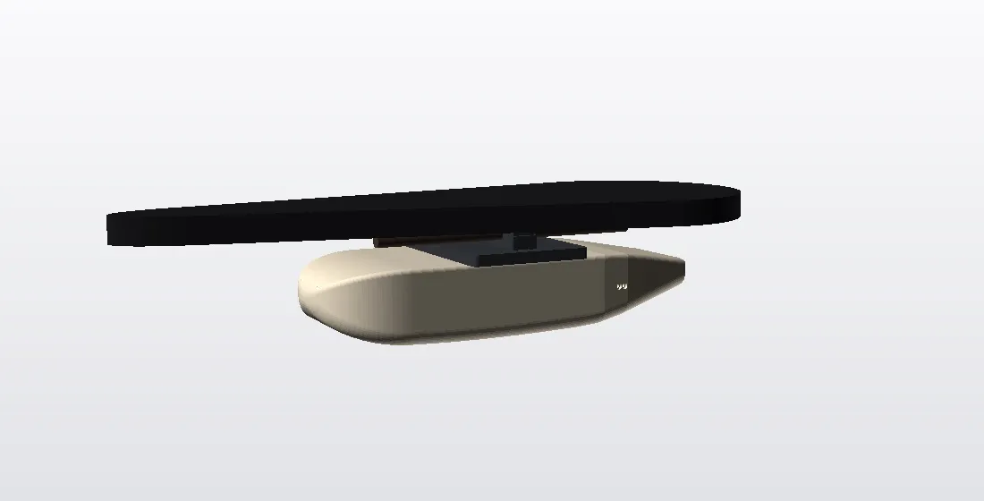
The clamp bridge is 68 × 92 mm and the four M4 feet are the least aerodynamic part of the system. The shell covers the clamp’s side flange and sits entirely below the rail plane, so the bridge forms the roof over it.
What we know, and what we do not
This is where the page has to be straight with you.
The frontal area grows from about 2,250 mm² (box plus flange) to about 3,370 mm², roughly 50 % more. That works against the second principle. Because the box sits in the rider’s wake, the effect may be small, but in the worst case the shell does not reduce total drag at all.
Nothing is measured. No CFD, no wind tunnel, no coast-down test. We give no watt and no drag figures, and we do not claim the shell makes anything faster. It is a shape built from sound rules, not a result.
Nothing is printed yet. The shell has been checked on screen for fit and wall thickness (at least 1.6 mm), and the 3D files export cleanly. The belly and the sloped tail floor need support when printed. The estimate is about 110 g of PETG.
Clearance is not measured: seatpost, saddle, thighs, rear wheel and saddlebag. The direction of travel is assumed. RF through 1.8 mm of PETG ahead of the antenna has not been bench-tested.
Sources
Some of these were read in full and some only as summaries, because the original was behind a paywall. The figures from Hoerner and Kamm describe elongated bodies and cars, so for a small box under a saddle they are qualitative guidance, not predictions.
| ID | Source | What it gives | How we read it |
|---|---|---|---|
| K1 | Kammback, Wikipedia (citing Kamm, 1938) | Cut the tail where the section is about 50 % of maximum; the separated wake imitates a longer tail. | Read |
| K2 | Trek, Kammtail Virtual Foil | A truncated tail behaves like a longer foil. A manufacturer claim with no watt figures. | Read; manufacturer claim |
| K3 | Crouch et al., review of competition cycling aerodynamics, and the 2014 wake study | The rider dominates drag; the wake behind the rider is large and turbulent. | Summary only (paywall) |
| K4 | TOUR Magazin wind-tunnel test and tri-mag on bottles behind the saddle | Items behind and under the rider are sensitive to height; higher placement is kinder. | Summary only, qualitative |
| K5 | Hoerner, Fluid-Dynamic Drag (1965), via summaries | Pressure drag is lowest near a length-to-diameter ratio of 3; a boat-tail separates beyond about 14 to 16°. | Summary only; book not read |
| K6 | Boat-tail angle figure and “Streamlined Tails”, truncation study | Supports about 15° as the limit and small losses from moderate truncation. | Summary only (paywall) |
What happens next
Next is a print and a fit check on a real bike, and then a coast-down test if it is worth the effort. Until then the honest line is the one we use everywhere: aero-shaped, not faster. If you ride with one, the lean-angle data is what matters, and that does not depend on the shell.
The shell is also described on the vision section of the front page.